Board of Pinout Diagram
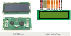
Pin Configuration
|
Pin No: |
Pin Name: |
Description |
|
1 |
Vss (Ground) |
Ground pin connected to system ground |
|
2 |
Vdd (+5 Volt) |
Powers the LCD with +5V (4.7V – 5.3V) |
|
3 |
VE (Contrast V) |
Decides the contrast level of display. Grounded to get maximum contrast. |
|
4 |
Register Select |
Connected to Microcontroller to shift between command/data register |
|
5 |
Read/Write |
Used to read or write data. Normally grounded to write data to LCD |
|
6 |
Enable |
Connected to Microcontroller Pin and toggled between 1 and 0 for data acknowledgement |
|
7 |
Data Pin 0 |
Data pins 0 to 7 forms a 8-bit data line. They can be connected to Microcontroller to send 8-bit data. These LCD’s can also operate on 4-bit mode in such case Data pin 4,5,6 and 7 will be left free. |
|
8 |
Data Pin 1 |
|
|
9 |
Data Pin 2 |
|
|
10 |
Data Pin 3 |
|
|
11 |
Data Pin 4 |
|
|
12 |
Data Pin 5 |
|
|
13 |
Data Pin 6 |
|
|
14 |
Data Pin 7 |
|
|
15 |
LED Positive |
Backlight LED pin positive terminal |
|
16 |
LED Negative |
Backlight LED pin negative terminal |
Features of 16×2 LCD module
- Operating Voltage is 4.7V to 5.3V
- Current consumption is 1mA without backlight
- Alphanumeric LCD display module, meaning can display alphabets and numbers
- Consists of two rows and each row can print 16 characters.
- Each character is build by a 5×8 pixel box
- Can work on both 8-bit and 4-bit mode
- It can also display any custom generated characters
- Available in Green and Blue Backlight
16×2 Display Equivalents
Dot Matrix LED Display, 7-Segment LED Display, OLED Display, TFT LCD Screen Display
Description on LCD modules
LCD modules are very commonly used in most embedded projects, the reason being its cheap price, availability and programmer friendly. Most of us would have come across these displays in our day to day life, either at PCO’s or calculators. The appearance and the pinouts have already been visualized above now let us get a bit technical.
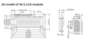
16×2 LCD is named so because; it has 16 Columns and 2 Rows. There are a lot of combinations available like, 8×1, 8×2, 10×2, 16×1, etc. but the most used one is the 16×2 LCD. So, it will have (16×2=32) 32 characters in total and each character will be made of 5×8 Pixel Dots. A Single character with all its Pixels is shown in the below picture.
Now, we know that each character has (5×8=40) 40 Pixels and for 32 Characters we will have (32×40) 1280 Pixels. Further, the LCD should also be instructed about the Position of the Pixels. Hence it will be a hectic task to handle everything with the help of MCU, hence an Interface IC like HD44780is used, which is mounted on the backside of the LCD Module itself. The function of this IC is to get the Commands and Data from the MCU and process them to display meaningful information onto our LCD Screen. You can learn how to interface an LCD using the above mentioned links. If you are an advanced programmer and would like to create your own library for interfacing your Microcontroller with this LCD module then you have to understand the HD44780 IC is working and commands which can be found its datasheet.
Component Datasheet PDF: 16×2 LCD Datasheet