The ARDUINO PRO MINI board is one of application boards. Since it is an application board it does not have in-built programmer. USB port and other connectors are also removed. Because once it is placed in an application programmer and connectors are basically useless.
ARDUINO PRO MINI is of two types they are differentiated based on CONTROLLER working voltage. One is +3.3V and another is +5V. Choose the appropriate board based on application.
Board of Pinout Diagram
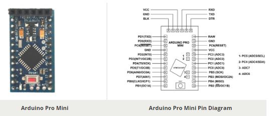
ARDUINO PRO MINI Pin Configuration
| PIN GROUP | PIN NAME | DESCRIPTION |
| POWER SOURCE | VCC, GND and RAW | VCC – Connected to +5V or +3.3V GND – Connected to GROUND RAW – Connected to Unregulated power supply 5+V to +12V |
| COMMUNICATION INTERFACE | UART Interface(RXD, TXD) SPI Interface(MOSI, MISO, SCK , SS ) TWI Interface(SDA, SCL) | UART (Universal Asynchronous Receiver Transmitter) Interface can be used to program PRO MINI SPI (Serial Peripheral Interface) Interface ban be used to program PRO MINI TWI (Two Wire Interface) Interface can be used to connect peripherals. |
| INPUT OUTPUT PINS | PD0 to PD7 (8 pins of PORTD) PB0 to PB5 (6 pins of PORTB) PC0 to PC6 (7 pins of PORTC) ADC6 and ADC7(2 additional pins) | Although these 23 pins have many functions they can be considered as data I/O pins. |
| ANALOG to DIGITAL CONVERTER | ADC0, ADC1, ADC2,…ADC7 | These channels can be used to input Analog signals. There are of 10 bit resolution. |
| PWM | OC0A,OC0B,OC1A,OC1B,OC2A,OC2B | These six channels can provide PWM (Pulse Width Modulation) outputs. They are of 8 bit resolution. |
| RESET | RESET | Resets the controller. |
| EXTERNAL INTERRUPTS | T0 and T1 | These two pins are specially designed hardware interrupts. |
| ANALOG COMPARATOR | AIN0 and AIN1 | These two pins are connected to internal comparator. |
ARDUINO PRO MINI Technical Specifications
| Microcontroller | Atmega328p – 8 BIT AVR controller |
| Operating Voltage | 5V and 3.3V |
| Raw Voltage input | 5V to 12V |
| Maximum current through each I/O pin | 40mA |
| Maximum total current drawn from chip | 200mA |
| Flash Memory | 32KBytes |
| EEPROM | 1KByte |
| Internal RAM | 2Kbytes |
| Clock Frequency | 3.3V — 8Mhz 5V — 16Mhz |
| Operating Temperature | -40ºC to +105ºC |
Similar ARDUINO Boards
ARDUINO UNO, ARDUINO MEGA, ARDUINO NANO, ARDUINO DUE, ARDUINO LEONARDO
Other Development Boards
RASPBERRY PI SERIES, INTEL GALILEO, INTEL EDISON, ESP32
Where to Use ARDUINO PRO MINI
All the ARDUINO boards are popular because of ease of understanding and application. Also the ARDUINO is an open source platform where one can get all related data and original module schematics. In this platform one can customize the system depending on the need.
There are many ARDUINO boards on the market. They are available with various features and packages. One can choose appropriate board depending on the need.
There are few cases where PRO MINI is chosen over other:
Case1: Where system is permanent installation. In permanent applications, the board only needs to be programmed once and that is all. In those cases features provided like USB programmer, I/O connectors and other supporting hardware is useless. The PRO MINI is specifically designed for those systems. This board has only basic hardware just enough for those applications.
Case2: For convenience. This board is one of smallest boards of ARDUINO. With its comfort size can be used in mobile applications.
Case3: With basic hardware the cost of board is considerable lesser.
Case4: With 32Kbytes memory the PRO MINI can accommodate most application programs.
How to Use ARDUINO PRO MINI
Using PRO MINI is similar to any other development board. All you need to do is program the controller and provide the appropriate peripheral to get system running. We will discuss the programming of PRO MINI in step by step below.
- First you need to gets a programmer. As mentioned earlier the PRO MINI does not have an inbuilt programmer, so you cannot connect PRO MINI directly to PC to program it. Choose either UART or SPI programmer. Preferable UART programmer.
- Download and install ARDUINO IDE software. [ https://www.arduino.cc/en/Main/Software ]
- List the functions to be performed by PRO MINI.
- Write the functions as program in IDE. Remember the program is written in ‘C’ language.
- Connect the programmer and establish a communication between IDE and PRO MINI.
- Burn the program to PRO MINI through IDE.
- Disconnect the programmer. Provide the power and attach the necessary peripherals. After reset the control executes the program and provides the desired output.
Applications
- Hobby projects.
- Power supply systems.
- IoT applications.
- Display systems.
| Component Datasheet PDF: Arduino Pro Mini Datasheet |