Now, a computers have become an integral part of life as they perform many tasks and operations in quite a short span of time.
One of the most important functions of the CPU in a computer is to perform logical operations by utilizing hardware like Integrated Circuits software technologies & electronic circuits.
But, how this hardware and software perform such operations is a mysterious puzzle.
In order to have a better understanding of such a complex issue, we must have to acquaint ourselves with the term Boolean Logic, developed by George Boole. For a simple operation, computers utilize binary digits rather than digital digits.
What is a Basic Logic Gates?
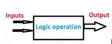
A logic gate is a basic building block of a digital circuit that has two inputs and one output, used to large Number no of Electronics Circuits.
- The relationship between the i/p and the o/p is based on a certain logic. These gates are implemented using electronic switches like transistors, diodes. But, in practice, basic logic gates are built using CMOS technology, FETS, and MOSFET(Metal Oxide Semiconductor FET)s.
- Logic gates are used in microprocessors, microcontrollers, embedded system applications, and in electronic and electrical project circuits. The basic logic gates are categorized into seven: AND, OR, XOR, NAND, NOR, XNOR, and NOT. These logic gates with their logic gate symbols and truth tables are explained below.
Why we use Basic Logic Gates?
The basic logic gates are used to perform fundamental logical functions. These are the basic building blocks in the digital ICs (integrated circuits). Most of the logic gates use two binary inputs and generates a single output like 1 or 0. In some electronic circuits, few logic gates are used whereas in some other circuits, microprocessors include millions of logic gates.
The implementation of Logic gates can be done through diodes, transistors, relays, molecules, and optics otherwise different mechanical elements. Because of this reason, basic logic gates are used like electronic circuits.
Binary & Decimal
Before talking about the truth tables of logic gates, it is essential to know the background of binary & decimal numbers. We all know the decimal numbers which we utilize in everyday calculations like 0 to 9. This kind of number system includes the base-10. In the same way, binary numbers like 0 and 1 can be utilized to signify decimal numbers wherever the base of the binary numbers is 2.
The significance of using binary numbers here is to signify the switching position otherwise voltage position of a digital component. Here 1 represents the High signal or high voltage whereas “0” specifies low voltage or low signal. Therefore, Boolean algebra was started. After that, each logic gate is discussed separately this contains the logic of the gate, truth table, and its typical symbol.
Types of logic Gates
The basic logic gates are classified into & 7 types:
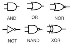
- AND gate,
- OR gate,
- NOT gate,
- NAND gate,
- NOR gate,
- Ex. OR gate, and Ex. NOR gate
AND Gate
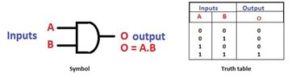
The AND gate is a digital logic gate with ‘n’ i/ps one o/p, which performs logical conjunction based on the combinations of its inputs. The output of this gate is true only when all the inputs are true. When one or more inputs of the AND gate’s i/ps are false, then only the output of the AND gate is false. The symbol and truth table of an AND gate with two inputs is shown below.
OR Gate
The OR gate is a digital logic gate with ‘n’ i/ps and one o/p, that performs logical conjunction based on the combinations of its inputs. The output of the OR gate is true only when one or more inputs are true. If all the i/ps of the gate are false, then only the output of the OR gate is false. The symbol and truth table of an OR gate with two inputs is shown below.

NOT Gate
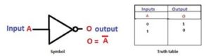
The NOT gate is a digital logic gate with one input and one output that operates an inverter operation of the input. The output of the NOT gate is the reverse of the input. When the input of the NOT gate is true then the output will be false and vice versa. The symbol and truth table of a NOT gate with one input is shown below. By using this gate, we can implement NOR and NAND gates
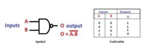
NAND Gate
The NAND gate is a digital logic gate with ‘n’ i/ps and one o/p, that performs the operation of the AND gate followed by the operation of the NOT gate.NAND gate is designed by combining the AND and NOT gates. If the input of the NAND gate high, then the output of the gate will be low.The symbol and truth table of the NAND gate with two inputs is shown below.
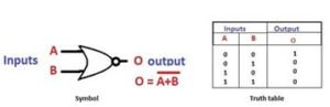
NOR Gate
The NOR gate is a digital logic gate with n inputs and one output, that performs the operation of the OR gate followed by the NOT gate. NOR gate is designed by combining the OR and NOT gate. When any one of the i/ps of the NOR gate is true, then the output of the NOR gate will be false. The symbol and truth table of the NOR gate with the truth table is shown below.
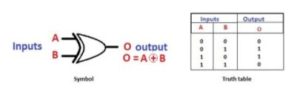
Exclusive-OR Gate
The Exclusive-OR gate is a digital logic gate with two inputs and one output. The short form of this gate is Ex-OR. It performs based on the operation of the OR gate. . If any one of the inputs of this gate is high, then the output of the EX-OR gate will be high. The symbol and truth table of the EX-OR are shown below.
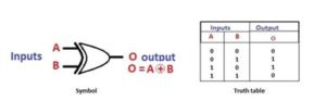
Exclusive-NOR Gate
The Exclusive-NOR gate is a digital logic gate with two inputs and one output. The short form of this gate is Ex-NOR. It performs based on the operation of the NOR gate. When both the inputs of this gate are high, then the output of the EX-NOR gate will be high. But, if any one of the inputs is high (but not both), then the output will be low. The symbol and truth table of the EX-NOR are shown below.
The applications of logic gates are mainly determined based upon their truth table, i.e., their mode of operations. The basic logic gates are used in many circuits like a push-button lock, light-activated burglar alarm, safety thermostat, an automatic watering system, etc.
Truth Table to Express Logic Gate Circuit
Gate circuit can be expressed using a common method is known as a truth table. This table includes all the input logic state combinations either high (1) or low (0) for every input terminal of the logic gate through the equivalent output logic level like high or low. The NOT logic gate circuit is shown above and its truth table is extremely easy indeed
The truth tables of logic gates are very complex but larger than the NOT gate. The truth table of each gate must include many rows like there are possibilities for exclusive combinations for inputs. For instance, for the NOT gate, there are two possibilities of inputs either 0 or 1, whereas, for the two-input logic gate, there are four possibilities like 00, 01, 10 & 11. Therefore, it includes four rows for the equivalent truth table.
For a 3-input logic gate, there are 8 possible inputs like 000, 001, 010, 011, 100, 101, 110 & 111. Therefore, a truth table including 8 rows is required. Mathematically, the required number of rows in the truth table is equivalent to 2 increased to the power of the no. of i/p terminals.
Analysis
The voltage signals in the digital circuits are represented with binary values like 0’s & 1’s calculated in reference to ground. The deficiency of voltage mainly signifies a “0” whereas the existence of full DC supply voltage signifies a “1”.
A logic gate is a special type of amplifier circuit that is mainly designed for input as well as output logic level voltages. Logic gate circuits are most frequently symbolized with a schematic diagram through their own exclusive symbols Instead of their essential resistors and transistors.
Just like with Op-Amps (operational amplifiers), the connections of power supply to logic gates are frequently misplaced in schematic diagrams for the benefit of simplicity. It includes the probable input logic level combinations through their particular output logic levels.
What is the Easiest Way to Learn Logic Gates?
The easiest way to learn the function of basic logic gates is explained below.
- For AND Gate – If both the inputs are high then the output is also high
- For OR Gate – If a minimum of one input is high then the output is High
- For XOR Gate – If the minimum one input is high then only the output is high
- NAND Gate – If the minimum one input is low then the output is high
- NOR Gate – If both the inputs are low then the output is high.
Applications
Basic logic gates are frequently used in
- circuits like a lock with push-button,
- The watering system automatically,
- burglar alarm activated through light,
- safety thermostat & other types of electronic devices.