Current transformer or Instrument transformers are used in electrical power system for step up and step down the current of the system for metering and protection purpose. Actually relays and meters used for protection and metering, are not designed for high currents and voltages.
High currents or voltages of electrical power system can not be directly fed to relays and meters. Current transformer steps down rated system current to 1 Amp or 5 Amp similarly voltage transformer steps down system voltages to 110 V. The relays and meters are generally designed for 1 Amp, 5 Amp and 110 V.
What is an Current Transformer?
A current transformer (CT) is an instrument transformer in which the secondary current is substantially proportional to primary current and differs in phase from it by ideally zero degree.
Construction of CT
The core of the current transformer is built up with lamination of silicon steel. For getting a high degree of accuracy the Permalloy or Mumetal is used for the making cores. The primary windings of the current transformers carry the current which is to be measured, and it is connected to the main circuit. The secondary windings of the transformer carry the current proportional to the current to be measured, and it is connected to the current windings of the meters or the instruments.
The primary and the secondary windings are insulated from the cores and each other. The primary winding is a single turn winding (also called a bar primary) and carries the full load current. The secondary winding of the transformers has a large number of turns.
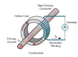
The ratio of the primary current and the secondary current is known as a current transformer ratio of the circuit. The current ratio of the transformer is usually high. The secondary current ratings are of the order of 5A, 1A and 0.1A. The current primary ratings vary from 10A to 3000A or more. The symbolic representation of the current transformer is shown in the figure below.

The working principle of the current transformer is slightly different from the power transformer. In a current transformer, the load’s impedance or burden on the secondary has slightly differed from the power transformers. Thus, the current transformer operates on secondary circuit conditions.
Working of Current Transformer(CT)
A CT functions with the same basic working principle of electrical power transformer, as we discussed earlier, but here is some difference. If a electrical power transformer or other general purpose transformer, primary current varies with load or secondary current. In case of CT, primary current is the system current and this primary current or system current transforms to the CT secondary, hence secondary current or burden current depends upon primary current of the current transformer.
In a power transformer, if load is disconnected, there will be only magnetizing current flows in the primary. The primary of the power transformer takes current from the source proportional to the load connected with secondary. But in case of CT, the primary is connected in series with power line. So current through its primary is nothing but the current flows through that power line.
The primary current of the CT, hence does not depend upon whether the load or burden is connected to the secondary or not or what is the impedance value of burden. Generally CT has very few turns in primary where as secondary turns is large in number. Say Np is number of turns in CT primary and Ip is the current through primary. Hence, the primary AT is equal to NpIp AT.
f number of turns in secondary and secondary current in that current transformer are Ns and Is respectively then Secondary AT is equal to NsIs AT.
In an ideal CT the primary AT is exactly is equal in magnitude to secondary AT.
So, from the above statement it is clear that if a CT has one turn in primary and 400 turns in secondary winding, if it has 400 A current in primary then it will have 1 A in secondary burden.
Thus the turn ratio of the CT is 400/1 A
Phasor Diagram of Current Transformer
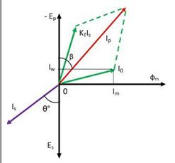
The phasor diagram of the current transformer is shown in the figure below. The main flux is taken as a reference. The primary and secondary induced voltages are lagging behind the main flux by 90º. The magnitude of the primary and secondary voltages depends on the number of turns on the windings. The excitation current induces by the components of magnetising and working current.
Where,
Is – secondary current
Es – secondary induced voltage
Ip -primary current
Ep – primary induced voltage
Kt – turn ratio, number of secondary turn/number of primary turn
I0 – excitation current
Im – magnetising current
Iw – working component
Φs – main flux
The secondary current lags behinds the secondary induced voltage by an angle θº. The secondary current relocates to the primary side by reversing the secondary current and multiply by the turn ratio. The current flows through the primary is the sum of the exciting current I0 and the product of the turn ratio and secondary current Kt Is.
Ratio and Phase Angle Errors of CT
The current transformer has two errors – ratio error and a phase angle error.
Current Ratio Errors – The current transformer is mainly due to the energy component of excitation current and is given as
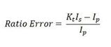
Where ,
Ip is the primary current. Kt is the turn ratio and is the secondary current.
Phase Angle Error – In an ideal current transformer the vector angle between the primary and reversed secondary current is zero. But in an actual current transformer, there is a phase difference between the primary and the secondary current because the primary current has also supplied the component of exciting current. Thus, the difference between the two phases is termed as a phase angle error.
How to Reduce Error in Current Transformer
It is desirable to reduce these errors, for better performance. For achieving minimum error in current transformer, one can follow the following,
- Using a core of high permeability and low hysteresis lossmagnetic materials.
- Keeping the rated burden to the nearer value of the actual burden.
- Ensuring minimum length of flux path and increasing cross-sectional area of the core, minimizing joint of the core.
- Lowering the secondary internal impedance.
Types of current Transformer
The current transformer is mainly classified into three types, i.e., wound current transformer, toroidal current transformer and bar-type transformers.
1. Wound Transformer – In this transformer the primary winding is composed inside the transformer. The primary winding had a single turn and connected in series with the conductor that measured the current. The wound transformer is mainly used for measuring the current from 1amps to 100 amps.
2. Bar-type Current Transformer – The bar type transformer has only secondary windings. The conductor on which the transformer is mounted will act as primary windings of the current transformers.
3.Toroidal Current Transformer – This transformer does not contain primary windings. The line through which the current flow in the network is attached through a hole or a window of the transformers. The major advantage of this transformer is that the transformer has a symmetrical shape due to which it has a low leakage flux, thus less electromagnetic interference.
Applications for Class 3 & Class 5 measuring current transformers include,
- Overload Protection
- Current Monitoring Three Phase Generators
- Control Devices
- Control Panels
- Switchgear control and monitoring
- Distribution
While it is desirable to have zero phase shift between primary and secondary current, for 5 A measuring CT’s it is not so important since ammeters only show the magnitude of the current.