Board of Pinout Diagram
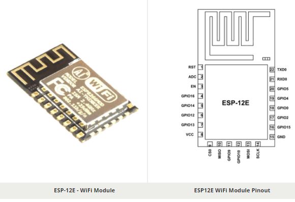
ESP-12E is a miniature Wi-Fi module present in the market and is used for establishing a wireless network connection for microcontroller or processor. The core of ESP-12E is ESP8266EX, which is a high integration wireless SoC (System on Chip). It features ability to embed Wi-Fi capabilities to systems or to function as a standalone application. It is a low cost solution for developing IoT applications.
Pin Configuration
The ESP-12E module has twenty two pins and we will describe function of each pin below.
| Pin | Name | Description |
| 1 | RST | Reset Pin of the module |
| 2 | ADC | Analog Input Pin for 10-bit ADC (0V to1V) |
| 3 | EN | Module Enable Pin (Active HIGH) |
| 4 | GPIO16 | General Purpose Input Output Pin 16 |
| 5 | GPIO14 | General Purpose Input Output Pin 14 |
| 6 | GPIO12 | General Purpose Input Output Pin 12 |
| 7 | GPIO13 | General Purpose Input Output Pin 13 |
| 8 | VDD | +3.3V Power Input |
| 9 | CS0 | Chip selection Pin of SPI interface |
| 10 | MISO | MISO Pin of SPI interface |
| 11 | GPIO9 | General Purpose Input Output Pin 9 |
| 12 | GPIO10 | General Purpose Input Output Pin 10 |
| 13 | MOSI | MOSI Pin of SPI interface |
| 14 | SCLK | Clock Pin of SPI interface |
| 15 | GND | Ground Pin |
| 16 | GPIO15 | General Purpose Input Output Pin 15 |
| 17 | GPIO2 | General Purpose Input Output Pin 2 |
| 18 | GPIO0 | General Purpose Input Output Pin 0 |
| 19 | GPIO4 | General Purpose Input Output Pin 4 |
| 20 | GPIO5 | General Purpose Input Output Pin 5 |
| 21 | RXD0 | UART0 RXD Pin |
| 22 | TXD0 | UART0 TXD Pin |
Features and Electrical Characteristics
- Wireless Standard: IEEE 802.11 b/g/n protocol
- Power Transmission:
| 802.11b | +16 ± 2 dBm |
| 802.11g | +14 ± 2 dBm |
| 802.11n | +13 ± 2 dBm |
- Frequency Range: 2.412 – 2.484 GHz
- Serial Transmission: 110 – 921600 bps, TCP Client 5
- SDIO 2.0, SPI and UART Interface available
- PWM available
- One ADC channel available
- Programmable GPIO available
- Wireless Network Type: STA / AP / STA + AP
- Security Type: WEP / WPA-PSK / WPA2-PSK
- Encryption Type: WEP64 / WEP128 / TKIP / AES
- Network Protocol: IPv4, TCP / UDP / FTP / HTTP
- Operating Voltage: 3.3V
- Maximum current allowed to draw per pin: 15mA
- Power down leakage current of < 10uA
- Integrated low power 32-bit MCU
- Onboard PCB Antenna
- Wake up and transmit packets in < 2ms
- Standby power consumption of < 1.0mW
- Operating Temperature: -40ºC to +125 ºC
Overview of ESP-12E
ESP-12E is a member of ‘ESP-XX’ series. Although all of them are based on ESP8266 SoC they differ in on output pins, flash memory and antenna type. These modules numbered from ESP-01 to ESP-15 and are best in performance and cost. Many engineers use these modules to setup a wireless communication between two applications. For data sharing and IoT you will find these modules Ideal.
How to use the ESP-12E
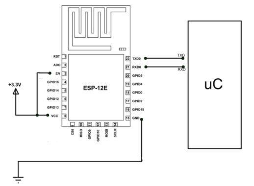
This module does not have complex circuitry or programming so using this module is very easy. We will construct a simple application circuit for understanding the module working.
Steps for setting up a simple application circuit:
- Connect positive +3.3V power to the module.
- Interface module to a microcontroller or ARDUINO using UART (Connect RXD of ESP to RXD of µC & TXD of ESP to TXD of µC).
- Download the libraries for the module from the internet. For ARDUINO, the IDE will have pre-installed libraries. If you do not have them just update the libraries from ARDUINO website.
- Write the program for setting up the baud rate and data exchange.
- Send data to the module for transmitting through Wi-Fi or Receive data from the module that was transmitted via Wi-Fi.
- There is another way for setting up the module which is to bypass microcontroller and directly connect the module to PC using FTDI. After interface you can use serial monitor to communicate with the module.
Applications
- Weather station
- IoT applications
- Home appliances
- Toys and Gaming applications
- Wireless control systems
- Home automation
- Security ID tags
Component Datasheet PDF: ESP12E WiFi Module Datasheet