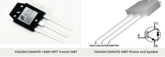
Board of Pinout Diagram

Pin Configuration
| Pin Name | Description |
| G | Gate, Controls the ON-OFF of the transistor |
| C | Collector, Current flows in through collector |
| E | Emitter, Current Drains out through emitter |
FGA25N120ANTD Features
- NPT Trench Technology, Positive temperature coefficient
- Low saturation voltage: VCE(sat), typ = 2.0V @ IC = 25A and TC = 25°C
- Low switching loss: Eoff, typ = 0.96mJ @ IC = 25A and TC = 25°C
- Extremely enhanced avalanche capability
- TO-3PN package
FGA25N120ANTD Alernative
FGA15N120FTD IGBT
Brief Description on FGA25N120ANTD
FGA25N120ANTD has Collector-Emitter Voltage VCES of 1200 V. It has Gate-Emitter Voltage VGES of range ± 20 V. The Collector Current IC at the temperature of 25°C is 50A and at the temperature of 100°C is 25A. The Pulsed Collector Current ICM is 90A. The Diode Maximum Forward Current IFM is 150 A. The Maximum Power Dissipation PD rating at 25°C is 312 W and Maximum Power Dissipation rating at 100°C is 125 W.
Where to use FGA25N120ANTD
The FGA25N120ANTD 1200V NPT (Nonpunch-Through) IGBT offers superior conduction and switching performances, high avalanche ruggedness and easy parallel operation. With a simpler device development process and lower switching losses, FGA25N120ANTD is well suited for the resonant or soft switching application such as induction heating, microwave oven.
How to use FGA25N120ANTD
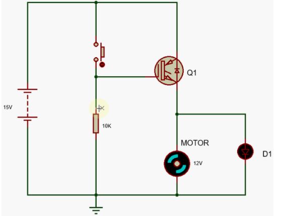
The Insulated Gate Bipolar Transistor (IGBT) can be switched ‘ON’ and ‘OFF’ by activating the gate. The circuit below shows the switching of the LED and Motor by giving input to the Gate terminal of the IGBT.

If we make the Gate more positive by applying voltage across the gate, the IGBT’s emitter keeps the IGBT in its “ON“ state and if we make the Gate negative or zero push the IGBT will remain in “OFF” state. It is same as like BJT and MOSFET switching.
Applications
- Induction Heating
- Microwave Oven
Component Datasheet PDF: FGA25N120ANTD 1200V NPT Trench IGBT Datasheet