Board of Pinout diagram

Pin Configuration
| Pin Number | Pin Name | Description |
| 1 | Emitter | Current Drains out through emitter |
| 2 | Base | Controls the biasing of transistor |
| 3 | Collector | Current flows in through collector |
Features
- Bi-Polar high current NPN Transistor
- DC Current Gain (hFE) is 100 to 300
- Continuous Collector current (IC) is 600mA
- Emitter Base Voltage (VBE) is 6V
- Collector Emitter Voltage (VCE) is 40V
- Base Current(IB) is 5mA maximum
- Available in To-92 Package
Note: Complete Technical Details can be found at the KSP2222A datasheet given at the end of this page.
KSP2222A Alternative Transistors
BC549, BC636, BC639, BC547, 2N2369, 2N3055, 2N3904, 2N3906, 2SC5200
KSP2222A Equivalent Transistor
2N2222A
Brief Description on KSP2222A Transistor
KSP2222A is a NPN transistor hence the collector and emitter will be left open (Reverse biased) when the base pin is held at ground and will be closed (Forward biased) when a signal is provided to base pin. KSP2222A has a gain value of 100 to 300, this value determines the amplification capacity of the transistor. The maximum amount of current that could flow through the Collector pin is 600mA, hence we cannot connect loads that consume more than 600mA using this transistor. To bias a transistor we have to supply current to base pin, this current (IB) should be limited to 5mA.
When this transistor is fully biased then it can allow a maximum of 600mA to flow across the collector and emitter. This stage is called Saturation Region and the typical voltage allowed across the Collector-Emitter (VCE) or Base-Emitter (VBE) could be 40V and 600mV respectively. When base current is removed the transistor becomes fully off, this stage is called as the Cut-off Region.
Where to use KSP2222A Transistor
The KSP2222A transistor is very much similar to the commonly used NPN transistor BC547. But there are two important features that distinguish both. KSP2222A can allow collector current upto 600mA and also has power dissipation of 625mW which can be used to drive larger loads than compared with BC547. It also has a Collector Emitter open Voltage (VCEo) of 40V.
So if you looking for an NPN transistor that could switch loads of higher current then KSP2222A might the right choice for your project.
How to use KSP2222A Transistor
The KSP222A transistor is a general purpose transistor and hence fit into many applications, it is a direct substitute for 2N2222A transistor since they both share almost the same properties except for the Continuous Collector Current (IC)rating and the Collector Emitter Voltage (VBE). Normally this type of transistor will either be used as a switch or as an amplifier, both of which is discussed below
Transistor as a Switch
One of the most default and primary function of a transistor is to act as a switch. It is very similar to a mechanical switch but here we will control the switch using electric signals. A very basic circuit diagram is given below in which a NPN transistor is used to turn ON or OFF a load (Motor).

The vales of the Resistor in the above image are only for reference and are not accurate. The resistor R1 is called the Base resistor and is very important to drive a transistor, it limits the base current and failing to use one might damage the transistor permanently. The transistor will begin to conduct when the voltage across the Base and Emitter pin exceeds 0.6V this voltage is called as threshold voltage. The resistor R2 is used to limit the current though the collector of the transistor and is not mandatory.
Transistor as Amplifier
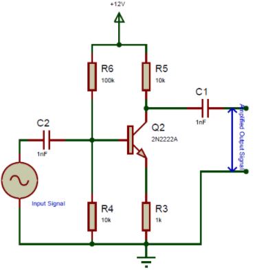
Another Common application of a Transistor is as amplifiers. Every transistor has a gain hFE associated with it, which can be used to amplify voltage or current. The below circuit diagram shows an NPN transistor being used in Common Emitter Amplifier mode. There are many types of amplifier circuits that are possible with transistor but this is the most commonly used one because it is very good in amplifying low frequency voltage signals like audio signals.

Again the values of the resistor mentioned above are only for reference (commonly used) you have to design your own circuit based on the application and transistor you are using.
In this type of circuit, the Emitter and the Base pin of the transistor should be commonly connected to a same voltage, so we have connected it to the Ground potential using two resistors R4 and R3. The base pin of the transistor has to be biased with a voltage; this voltage is provided by the potential divider network formed by the resistors R4 and R6. The capacitors C1 and C2 are simply used for filtering purpose. However this type of amplifiers have many drawback and if you are looking for some serious amplification applications then you should look into Op-Amps which are nothing but a package of many transistors put to gather with amplification as its sole purpose.
Applications
- General purpose NPN transistor
- Can be used to switch high current (upto 600mA) loads
- It can also be used in the various switching applications.
- Speed control of Motors
- Inverter and other rectifier circuits
- Can be used in Darlington Pair.
Component Datasheet PDF: KSP2222A Transistor Datasheet