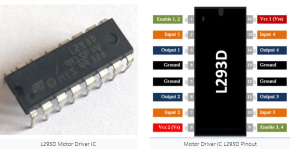
L293D Pin Configuration
| Pin Number | Pin Name | Description |
| 1 | Enable 1,2 | This pin enables the input pin Input 1(2) and Input 2(7) |
| 2 | Input 1 | Directly controls the Output 1 pin. Controlled by digital circuits |
| 3 | Output 1 | Connected to one end of Motor 1 |
| 4 | Ground | Ground pins are connected to ground of circuit (0V) |
| 5 | Ground | Ground pins are connected to ground of circuit (0V) |
| 6 | Output 2 | Connected to another end of Motor 1 |
| 7 | Input 2 | Directly controls the Output 2 pin. Controlled by digital circuits |
| 8 | Vcc2 (Vs) | Connected to Voltage pin for running motors (4.5V to 36V) |
| 9 | Enable 3,4 | This pin enables the input pin Input 3(10) and Input 4(15) |
| 10 | Input 3 | Directly controls the Output 3 pin. Controlled by digital circuits |
| 11 | Output 3 | Connected to one end of Motor 2 |
| 12 | Ground | Ground pins are connected to ground of circuit (0V) |
| 13 | Ground | Ground pins are connected to ground of circuit (0V) |
| 14 | Output 4 | Connected to another end of Motor 2 |
| 15 | Input 4 | Directly controls the Output 4 pin. Controlled by digital circuits |
| 16 | Vcc2 (Vss) | Connected to +5V to enable IC function |
Features
- Can be used to run Two DC motors with the same IC.
- Speed and Direction control is possible
- Motor voltage Vcc2 (Vs): 4.5V to 36V
- Maximum Peak motor current: 1.2A
- Maximum Continuous Motor Current: 600mA
- Supply Voltage to Vcc1(vss): 4.5V to 7V
- Transition time: 300ns (at 5Vand 24V)
- Automatic Thermal shutdown is available
- Available in 16-pin DIP, TSSOP, SOIC packages
Note: Complete Technical Details can be found at the L293D datasheet given at the end of this page.
L293D Equivalent Dual Timer IC
LB1909MC, SN754410, ULN2003
Where to use L293D IC
The L293D is a popular 16-Pin Motor Driver IC. As the name suggests it is mainly used to drive motors. A single L293D IC is capable of running two DC motors at the same time; also the direction of these two motors can be controlled independently. So if you have motors which has operating voltage less than 36V and operating current less than 600mA, which are to be controlled by digital circuits like Op-Amp, 555 timers, digital gates or even Micron rollers like Arduino, PIC, ARM etc.. this IC will be the right choice for you.
How to use a L293D Motor Driver IC
Using this L293D motor driver IC is very simple. The IC works on the principle of Half H-Bridge, let us not go too deep into what H-Bridge means, but for now just know that H bridge is a set up which is used to run motors both in clock wise and anti clockwise direction. As said earlier this IC is capable of running two motors at the any direction at the same time, the circuit to achieve the same is shown below.
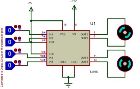
All the Ground pins should be grounded. There are two power pins for this IC, one is the Vss(Vcc1) which provides the voltage for the IC to work, this must be connected to +5V. The other is Vs(Vcc2) which provides voltage for the motors to run, based on the specification of your motor you can connect this pin to anywhere between 4.5V to 36V, here I have connected to +12V.
The Enable pins (Enable 1,2 and Enable 3,4) are used to Enable Input pins for Motor 1 and Motor 2 respectively. Since in most cases we will be using both the motors both the pins are held high by default by connecting to +5V supply. The input pins Input 1,2 are used to control the motor 1 and Input pins 3,4 are used to control the Motor 2. The input pins are connected to the any Digital circuit or microcontroller to control the speed and direction of the motor. You can toggle the input pins based on the following table to control your motor.
| Input 1 = HIGH(5v) | Output 1 = HIGH | Motor 1 rotates in Clock wise Direction |
| Input 2 = LOW(0v) | Output 2 = LOW | |
| Input 3 = HIGH(5v) | Output 1 = HIGH | Motor 2 rotates in Clock wise Direction |
| Input 4 = LOW(0v) | Output 2 = LOW |
| Input 1 = LOW(0v) | Output 1 = LOW | Motor 1 rotates in Anti-Clock wise Direction |
| Input 2 = HIGH(5v) | Output 2 = HIGH | |
| Input 3 = LOW(0v) | Output 1 = LOW | Motor 2 rotates in Anti -Clock wise Direction |
| Input 4 = HIGH(5v) | Output 2 = HIGH |
| Input 1 = HIGH(5v) | Output 1 = HIGH | Motor 1 stays still |
| Input 2 = HIGH(5v) | Output 2 = HIGH | |
| Input 3 = HIGH(5v) | Output 1 = LOW | Motor 2 stays still |
| Input 4 = HIGH(5v) | Output 2 = HIGH |
Applications
- Used to drive high current Motors using Digital Circuits
- Can be used to drive Stepper motors
- High current LED’s can be driven
- Relay Driver module (Latching Relay is possible)
2D Model of L293D (PDIP)
