LM4558 is an IC consists of Two General Purpose Operational Amplifiers and is a member of ‘LMxx’ family. The LM series originated with integrated circuits made by National Semiconductor. The prefix LM stands for linear monolithic, referring to the analog components integrated onto a single piece of silicon. The chip is short circuit protected and the internal frequency compensation ensures stability without external components.

LM4558 Pin configuration
LM4558 is a 8 pin device as shown in above pin diagram and description for each pin is given below.
|
Pin |
Name |
Description |
|
1 |
1OUT |
Output pin of the Op-amp 1 |
|
2 |
1IN- |
Inverting input of Op-amp 1 |
|
3 |
1IN+ |
Non-Inverting input of Op-amp 1 |
|
4 |
GND |
Ground |
|
5 |
2IN+ |
Non-Inverting input of Op-amp 2 |
|
6 |
2IN- |
Inverting input of Op-amp 2 |
|
7 |
2OUT |
Output pin of the Op-amp 2 |
|
8 |
VCC |
Power supply |
The device is available in many packages the user can choose depending on requirement.
Features and Electrical characteristics of LM4558 IC
- Two individually operated operational amplifiers
- Low noise interference among op-amps
- Continuous Short-Circuit Protection
- No frequency Compensation Required
- No latch-up
- Large common mode and differential voltage range
- Gain and phase match between amplifiers
- Low noise input transistors
- Moisture Sensitivity Level 3
- Parameter tracking over temperature range
- CMRR (Common-Mode Rejection Ratio): 80dB
- Single Supply Operation: +5.0 V to +15 V
- Dual Supply Operation: +15V and -15V
- Operating temperature: 0ºC to 70ºC
- Total power dissipation: 200mW
Op-Amp ICs Similar to LM4558
LM158, LM258, LM358, LM2904, LM747

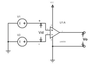
As mentioned earlier we can use these two op-amps to realize most of op-amp based circuits like comparator, differential amplification and mathematical operations. We will use op-amp to construct a simple comparator circuit to understanding the working of op-amp. Now let us take a single op-amp from the two and construct a simple application circuit as show below.

In the circuit a comparison between voltages V1 and V2 is done by the device and an output is provided as Vo. Also the device is powered from single voltage source of VCC.
In the circuit, Vid = V1 – V2
If Vid >0 then Vo = VCC
If Vid<0 then Vo = 0V or GND
Based on the state of the output we can determine whether Vid is positive or negative and also whether V1 is higher or V2 is higher at the input. With the higher voltage being know by knowing the output the function of op-amp as a comparator is done.
Applications
- Mathematical operations
- Amplifiers
- Oscillators
- Voltage comparators
- Peak detectors
- Logic voltage translation
- Industrial
- Measuring instruments