NEMA 17 is a hybrid stepping motor with a 1.8° step angle (200 steps/revolution). Each phase draws 1.2 A at 4 V, allowing for a holding torque of 3.2 kg-cm. NEMA 17 Stepper motor is generally used in Printers, CNC machines and Laser Cutters.
Pin Configuration
| NO. | Pin Name | WireColour | Description |
| 1 | Coil 1 | Black | This motor has six wires, connected to two split windings. Black, Yellow, Green wires is part of first winding while Red, White and Blue is part of second winding. |
| 2 | Coil 2 | Yellow | |
| 3 | Coil 3 | Green | |
| 4 | Coil 4 | Red | |
| 5 | Coil 5 | White | |
| 6 | Coil 6 | Blue |
NEMA 17 Stepper Motor Technical Specifications
- Rated Voltage: 12V DC
- Current: 1.2A at 4V
- Step Angle: 1.8 deg.
- No. of Phases: 4
- Motor Length: 1.54 inches
- 4-wire, 8 inch lead
- 200 steps per revolution, 1.8 degrees
- Operating Temperature: -10 to 40 °C
- Unipolar Holding Torque: 22.2 oz-in
Note: The NEMA17 stepper motor datasheet can be found at the bottom of the page.
Other Stepper motors
Nema23, Nema34, 28BYJ-48 Stepper Motor
Other Motors
DC Motor, 12V DC motor, Servo Motor, BLDC Motor
Where to use NEMA 17 Stepper Motor
NEMA17 Stepper Motor is commonly used in CNC machines, Hard Drives and Linear Actuators. The motor have 6 lead wires and rated voltage is 12 volt. It can be operated at lower voltage but torque will drop. These motors has a step angle of 1.8 deg., this means that it has 200 steps per revolution for every step it will cover a 1.8° hence the level of control is also high. These motors run on 12V and hence can provide high torque. So if you are looking for a compact easy to use stepper motor with high torque then this motor is the right choice for you.
How to use 28-BYJ48 Stepper Motor
These stepper motors consume high current and hence a driver IC like the A4988 is mandatory. To know how to make this motor rotate we should look into the coil diagram below.
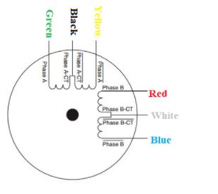
The motor has six wires, connected to two split windings as is common for unipolar stepper motors. Black, Yellow, Green wires is part of first winding where Black is centre tap and Yellow and Green are coil end while Red, White and Blue is part of second winding in which White is centre tap and Red and Blue are coil end wires. In use, the centre taps of the windings (Black and White) are typically wired to the positive supply, and the two ends of each winding are alternately grounded through a drive circuit. As shown in the wiring diagram the order of the stator poles in the motor is A, B, A’, B’.
Stepper Motor Applications
- CNC machines
- Precise control machines
- 3D printer/prototyping machines (e.g. RepRap)
- Laser cutters
- Pick and place machines
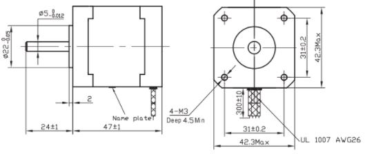
NEMA17 Dimensions