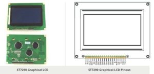
Pin Configuration
|
Pin No. |
Pin Name |
Description |
|
1 |
Gnd |
Ground terminal |
|
2 |
Vcc |
Positive Input Voltage terminal |
|
3 |
Vo |
LCD contrast |
|
4 |
RS |
Register Select RS = 0: Instruction Register RS = 1: Register Read |
|
5 |
R/W |
Read/Write control |
|
6 |
E |
Enable |
|
7 |
DB0 |
|
|
8 |
DB1 |
|
|
9 |
DB2 |
|
|
10 |
DB3 |
Data Pins for 8/4 bit Parallel mode |
|
11 |
DB4 |
|
|
12 |
DB5 |
|
|
13 |
DB6 |
|
|
14 |
DB7 |
|
|
15 |
PSB |
Interface selection: Low(0) – serial communication mode High (1) – 8/4-bit parallel bus mode. |
|
16 |
NC |
Not connected |
|
17 |
RST |
Reset |
|
18 |
Vout |
LCD voltage doubler output. VOUT ≦ 7V. |
|
19 |
BLA |
Backlight positive supply |
|
20 |
BLK |
Backlight Negative supply |
Features and Specification
- Operating Voltage: 5V
- Viewing angle: 6 ‘o’ clock
- MCU I/F: Serial or 8-bit parallel
- Display Color: Blue
- ST7290 LCD controller/driver IC
- Low power consumption
- Automatic power on Reset
- Graphic and Character mix modes display
- Built-in Voltage booster
- Display Construction: 128*64 dots
- Display Mode: STN
- Type: Chip On Board (COB)
Block Diagram
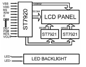
The image below shows the block diagram or internal structure of Graphical LCD. The controller used for the LCD is ST7290 LCD controller.
Where Graphical LCD are used?
A graphical LCD can be used in various electronic equipment where we need to display some character or image. Basically, these type of display used in medical, hand-held, security or industrial equipment. Also, Graphical LCD are used in various electronic DIY projects. It’s easy to interface it with micro-controller, Arduino and other controllers.
How to Use ST7290 GLCD?
There are two mode of interface in Graphical LCD:
- Serial Mode
- 8/4-bit Mode
Serial Mode:
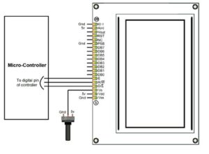
To use in serial mode, you just have to ground PSB Pin which change the interface of Graphical LCD into serial as shown in image below:
8/4-bit Mode:
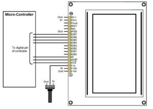
To use in 8/4- bit Mode, you just have to connect the PSB to positive supply or 5v, which change the interface into parallel mode as shown in image below:
Graphical LCD with Arduino
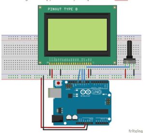
As used in various electronic projects, generally we use Arduino to interface our Graphical LCD. When you are using a Graphical LCD with Arduino, I advise you to use it in serial mode, which will decrease the use of no. of pins. The below circuit diagram will help you to connect your Graphical LCD with Arduino in serial mode.
Applications
- Industrial devices
- Embedded Systems
- Security
- Medical
- Hand-held equipment
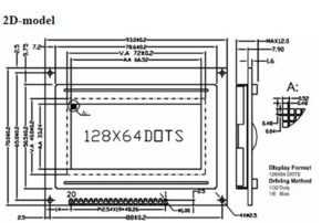
Component Datasheet PDF: ST7290 GLCD Datasheet