The term SCR stands for silicon controlled rectifier which is one of the most important members of the thyristor family. It is more popular than the other Thyristors like TRIAC, SCS, DIAC, etc. that some people even use the words Thyristor and SCR interchangeably. So next time when someone says just “Thyristor” in general, then they are referring to the SCR.
SCRs are constructed from silicon and are most commonly used for converting AC current to DC current (rectification), hence the name Silicon controlled rectifier. They are also used in other applications such as regulation of power, inversion, etc. The SCRs have an ability to handle high value of current and Voltage hence they are used in most of the industrial applications.
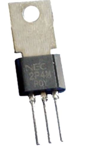
Physical Component of SCR
SCR Symbol
The Symbol of the SCR will be similar to that of the diode, additionally; it has a gate terminal as shown below. The SCR is a unidirectional device that allows the current to flow in one direction and opposes it in another direction. SCR has three terminals namely Anode (A), Cathode (K) and gate (G), it can be turned ON or OFF by controlling the biasing conditions or the gate input.

Again the Thyristor symbol and SCR symbol are the same. Now that we know how an SCR/Thyristor can be represented in a circuit diagram, let’s look into the SCR Construction and Working to understand more about it.
Construction of SCR
The SCR is a four-layered semiconductor device that forms NPNP or PNPN structure, which eventually forms three junctions J1, J2, and J3. Among the three terminals of the SCR, the Anode is a positive electrode, it will be on the P-layer and Cathode is a negative electrode, it will be on the N-layer of the SCR, the Gate acts as a control terminal of the SCR. The SCR Construction image is shown below.
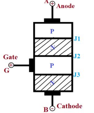
The outer P and N layers where the two electrodes are placed will be heavily doped and the middle P and N layers will be lightly doped, the gate terminal will be connected to the P-layer in the middle. The SCRs are constructed with three different types, planar type, Mesa type, and Press pack type.
SCR working Principle
To understand the SCR working principle we have to look into the different ways it can operate. Depending on the polarity of the voltage applied and the gate pulse given to the SCR, it can operate in three different modes such as
- Forward Blocking mode
- Forward Conduction mode
- Reverse Blocking mode
Now, let’s understand the Thyristor working by taking a look at each of the operating modes with its circuit diagram.
Forward Blocking Mode
In this mode of operation, the positive voltage is applied to the anode and the negative voltage applied to the cathode, there will not be any pulse applied to the gate, it will be kept in the open state. Once the voltage is applied, the junctions J1 and J3 will be forward biased and the junction J2 will be reverse biased. Since J2 is reverse biased the width of the depletion region increases and it acts as an obstacle for conduction, so only a small amount of current will be flowing from J1 to J3.

When the voltage applied to the SCR is increased and if it reaches the breakdown voltage of the SCR, the junction J2 gets depleted due to avalanche breakdown. Once the Avalanche breakdown occurs the current will start flowing through the SCR. In this mode of operation, the SCR is forward biased, but, there will not be any current flow.
Forward Conduction Mode
The Forward Conduction Mode is the only mode at which the SCR will be in the ON state and will be conducting. We can make the SCR conduct in two different ways, one we can increase the applied forward bias voltage beyond the breakdown voltage or else we can apply a positive voltage to the gate terminal.
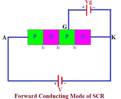
When we increase the Applied forward bias voltage between the anode and cathode the junction J2 will be depleted due to the avalanche breakdown and the SCR will start conducting. We are not able to do this for all the applications and this method of activating the SCR will eventually reduce the lifetime of the SCR.
If you want to use the SCR for low voltage applications you can apply a positive voltage to the gate of the SCR. The applied positive voltage will help the SCR to move to the conduction state. During this mode of operation, the SCR will be operating in forward bias and current will be flowing through it.
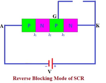
Reverse Blocking Mode
In the reverse blocking mode, the positive voltage is applied to the Cathode (-) and the Negative voltage is given to the Anode (+), There will not be any pulse given to the gate, it will be kept as an open circuit. During this mode of operation the Junctions J1 and J3 will be reverse biased and the junction J2 will be forward biased. Since the junctions J1 and J3 are reverse biased there will not be any current flowing through the SCR. Although there will be a small leakage current flowing due to the drift charge carriers in the forward-biased Junction J2, it is not enough to turn on the SCR.
VI Characteristics of SCR
The VI characteristics of the SCR are obtained by operating the SCR in three different regions, namely forward blocking region, forward conduction region and reverse blocking region

When the SCR is operating in the reverse blocking mode, there will be small leakage current flowing in the reverse direction of the SCR which is mentioned as the reverse leakage current in the graph, the reverse leakage current will be located at the negative quadrants of the graph.
Now if you apply positive voltage to anode and negative voltage to cathode the SCR will start operating in the forward blocking mode and a small leakage current will be flowing through the SCR in the positive direction, hence the curve starts rising to a certain level in the positive quadrants of the graph which is mentioned as the forward leakage current.
Once the graph reaches a certain voltage level called the Breakdown voltage or if the gate current Ig is applied to the SCR, the SCR moves to the conduction mode and a high amount of current starts flowing through the SCR. The current flow is represented as the forward conduction in the VI curve. The gate current applied are mentioned as Ig1, Ig2 and Ig3, higher the applied gate current faster the SCR goes to the conduction state as Ig3 > Ig2 > Ig1.
SCR Applications
From Converter circuits to Control circuits, SCRs are used in a wide range of applications. It is not possible to discuss all the Thyristor applications, but basically, they are used to control the current or voltage across a device. For example, let’s consider an example where SCRs are used to control the speed of a motor.
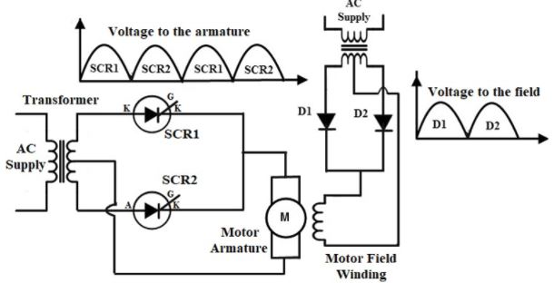
The above circuit diagram of SCR shows the arrangement for controlling the speed of a DC motor using the SCR. The motor will be having two windings namely field winding and armature winding. By controlling the current given to the armature winding we can control the speed of the DC motor. The armature winding of the motor is connected to an AC supply through a transformer and two SCRs connected in parallel with one another.
During the positive half cycle of the AC supply, the SCR1 is forward biased and starts conducting if the gate pulse is applied, the current to the armature winding will be flowing through the SCR1. Similarly, during the negative half cycle of the AC supply, the SCR2 is forward biased and SCR1 will be reverse biased and hence the SCR1 goes to the OFF state, when the gate pulse is applied to SCR2 it starts, conducting. By varying the trigger pulse given to the gates of the respective SCRs we will be able to control the input given to the DC motor hence it controls the speed of the motor.