Board of Pinout Diagram
The SIM900A is a readily available GSM/GPRS module,used in many mobile phones and PDA. The module can also be used for developing IOT (Internet of Things) and Embedded Applications. SIM900A is a dual-band GSM/GPRS engine that works on frequencies EGSM 900MHz and DCS 1800MHz. SIM900A features GPRS multi-slot class 10/ class 8 (optional) and supports the GPRS coding schemes CS-1, CS-2, CS-3 and CS-4.
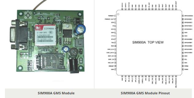
SIM900A GSM Module Pinout Configuration
SIM900A is a 68 terminal device as shown in pin diagram. We will describe the function of each pin below.
| Pin Number | Pin Name | Description |
| 1 | PWRKEY | Voltage input for PWRKEY. PWRKEY should be pulled low to power on or power off the system.The user should keep pressing the key for a short time when power on or power off the system because the system need margin time in order to assert the software. |
| 2 | PWRKEY_OUT | Connecting PWRKEY and PWRKEY_OUT for a short time then release also can power on or power off the module. |
| 3 | DTR | Data terminal Ready [Serial port ] |
| 4 | RI | Ring indicator [Serial port ] |
| 5 | DCD | Data carry detect [Serial port ] |
| 6 | DSR | Data Set Ready [Serial port ] |
| 7 | CTS | Clear to send [Serial port ] |
| 8 | RTS | Request to send [Serial port ] |
| 9 | TXD | Transmit data [Serial port ] |
| 10 | RXD | Receive data [Serial port ] |
| 11 | DISP _CLK | Clock for display [Display interface] |
| 12 | DISP_DATA | Display data output [Display interface] |
| 13 | DISP _D/C | Display data or command select [Display interface] |
| 14 | DISP _CS | Display Enable [Display interface] |
| 15 | VDD_EXT | 2.8V output power supply |
| 16 | NRESET | External reset input |
| 17,18,29,39,45,46,53,54,58,59,61,62,63,64,65 | GND | Ground |
| 19 | MIC_P | Microphone Positive |
| 20 | MIC_N | Microphone Negative |
| 21 | SPK_P | Speaker Positive |
| 22 | SPK_N | Speaker Negative |
| 23 | LINEIN_R | Right Channel input [External line inputs are available to directly mix or multiplex externally generated analog signals such as polyphonic tones from an external melody IC or music generated by an FM tuner IC or module.] |
| 24 | LINEIN_L | Left Channel Input |
| 25 | ADC | General purpose analog to digital converter. |
| 26 | VRTC | Current input for RTC when the battery is not supplied for the system.Current output for backup battery when the main battery is present and the backup battery is in low voltage state. |
| 27 | DBG_TXD | Transmit pin [Serial interface for debugging and firmware upgrade ] |
| 28 | DBG_RXD | Receive pin [Serial interface for debugging and firmware upgrade ] |
| 30 | SIM_VDD | Voltage supply for SIM card |
| 31 | SIM_DATA | SIM data output |
| 32 | SIM_CLK | SIM clock |
| 33 | SIM_RST | SIM reset |
| 34 | SIM_PRESENCE | SIM detect |
| 35 | PWM1 | PWM Output |
| 36 | PWM2 | PWM Output |
| 37 | SDA | Serial Data [I2C] |
| 38 | SCL | Serial Clock [I2C] |
| 40,41,42,43,44&47,48,49,50,51 | KBR0 to KBR4&KBC4 to KBC0 | Keypad interface [ROWS & COLUMNS] |
| 52 | NETLIGHT | Indicate net status |
| 55,56,57 | VBAT | Three VBAT pins are dedicated to connect the supply voltage. The power supply of SIM900A has to be a single voltage source of VBAT= 3.4V to 4.5V. It must be able to provide sufficient current in a transmit burst which typically rises to 2A. |
| 60 | RF_ANT | Antenna connection |
| 66 | STATUS | Indicate working status |
| 67 | GPIO 11 | General Purpose Input/output |
| 68 | GPIO 12 | General Purpose Input/output |
SIM900A GSM MODULE Features
- Single supply voltage: 3.4V – 4.5V
- Power saving mode: Typical power consumption in SLEEP mode is 1.5mA
- Frequency bands:SIM900A Dual-band: EGSM900, DCS1800. The SIM900A can search the two frequency bands automatically. The frequency bands also can be set by AT command.
- GSM class: Small MS
- GPRS connectivity:GPRS multi-slot class 10 (default) , GPRS multi-slot class 8 (option)
- Transmitting power: Class 4 (2W) at EGSM 900, Class 1 (1W) at DCS 1800
- Operating Temperature: -30ºC to +80ºC
- Storage Temperature: -5ºC to +90ºC
- DATA GPRS: download transfer max is 85.6KBps, Upload transfer max 42.8KBps
- Supports CSD, USSD, SMS, FAX
- Supports MIC and Audio Input
- Speaker Input
- Features keypad interface
- Features display interface
- Features Real Time Clock
- Supports UART interface
- Supports single SIM card
- Firmware upgrade by debug port
- Communication by using AT commands
Similar Modules
SIM800L, QUECTEL M95
How to Use SIM900A Module
For understanding the usage of the module let us consider a simple application circuit as shown below.

the communication with this module is done through UART or RS232 Interface. The data is sent to the module or received from the module though UART interface.
The module is typically connected to +4.0V standard power supply. It can work on +4.5V regulated power and any higher voltage may damage the module. And the power source should be able to deliver a peak current of 2A. The UART interface is established as shown in figure. All you need to do is connect RXD of module to TXD of Arduino and TXD is connected to RXD of ARDUINO. The ground of controller and module must be connected for voltage reference. Here AUDIO IN is connected to MIC and AUDIO OUT is connected to a speaker or headset. And at last we need to connect a working GSM SIM card to the module. On powering the module the NETLIGHT LED will blink periodically to state successful connection.
After all connections are done,we need to write a program for the microcontroller to exchange data with module. Since data exchange sequence between controller and module is really complex we will use libraries prewritten for the module. You can download libraries for controller or module through their websites. Using these libraries makes the communication easy. All you need to do is download these libraries and call them in programs. Once the header file is included, you can use simple commands in the program to tell the controller to send or receive data. The controller sendsthe data to the module through UART Interface based on protocol setup in libraries. The module sends this data to another GSM user using cellular network. If the module receives any data from the cellular network (or another GSM user) it will transmit it to controller through UART serial communication.
This way we can use GSM900A module to establish cellular connection.
Applications
- Cellular Communication
- Robotics
- Mobile Phone Accessories
- Servers
- Computer Peripherals
- Automobile
- USB Dongles
Component Datasheet PDF : SIM900A GSM Module Datasheet